Voltage drop isn't a one-time number you calculate and forget. Cable ages, loads change, connections loosen, and installations get extended over time, all of which can push a circuit's voltage drop closer to, or past, its compliant limit.
Tracking voltage drop means understanding what causes it, checking it at the right points in a system's life, and using the right tools to keep it within the limits set by AS/NZS 3000:2018. This guide covers exactly how to do that, from the factors that influence voltage drop to the methods and tools used to monitor it over time.
What Does “Tracking Voltage Drop” Mean?
Voltage drop is the loss of voltage that occurs as current travels through a conductor, caused by the conductor's resistance. Tracking it covers two related jobs:
- Calculating it accurately at the design stage, before a cable is installed.
- Monitoring it over time, since real-world conditions can shift voltage drop away from its original design figures.
Both matter. A circuit that was compliant when installed can drift out of compliance years later if nothing is tracked or reviewed.
Why Tracking Voltage Drop Matter
Under Clause 3.6 of AS/NZS 3000:2018, voltage drop must not exceed 5% of nominal voltage between the point of supply and any point in the installation. Staying within that limit needs to hold up for the life of the installation.
Tracking voltage drop properly helps you:
- Catch compliance drift before it causes a failed inspection
- Identify circuits at risk before equipment is damaged or a fire hazard develops
- Make informed decisions when adding loads, extending circuits, or upgrading equipment
- Keep documented, defensible records for audits, warranty claims, or client handover
What Are the Key Factors that Affect Voltage Drop?
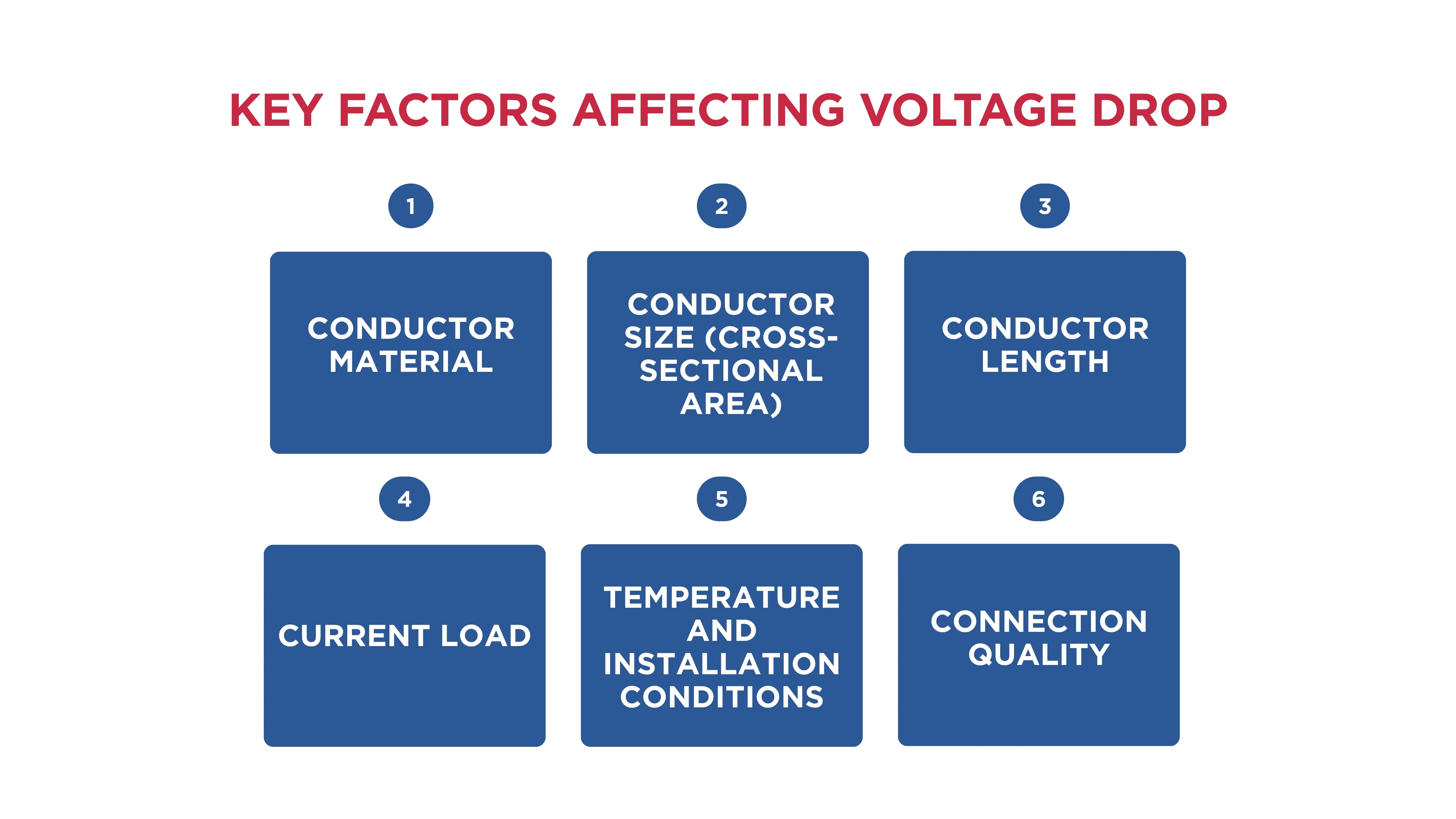
Tracking voltage drop starts with understanding what moves the number. Six factors do most of the work:
Conductor Material
Copper has lower resistance than aluminium, so copper conductors generally produce less voltage drop for the same size and length.
Aluminium is still widely used in cost-sensitive or large-scale applications, but it typically needs a larger cross-section to achieve a comparable result.
Conductor Size (Cross-Sectional Area)
Larger conductors have lower resistance. Upgrading from, say, a 2.5 mm² cable to a 4 mm² cable on a high-current circuit can noticeably reduce voltage drop. This is why cable size is the most common lever used to bring a circuit back into compliance.
Conductor Length
The longer the cable run, the more resistance the current encounters, and the greater the voltage drop. This is one of the first things to re-check when tracking voltage drop on a system that's been extended or had equipment relocated further from the switchboard.
Current Load
Voltage drop rises in proportion to current. A circuit that was compliant under its original load can drift out of compliance if additional equipment increases the current it now carries. This is exactly why load changes should trigger a re-check.
Temperature and Installation Conditions
Higher ambient and conductor temperatures increase resistance, which increases voltage drop. Installation method matters too, and AS/NZS 3008.1.1 applies different correction factors depending on the method used.
Connection Quality
Loose, corroded, or poorly terminated connections add resistance at specific points in a circuit, rather than along its length. This is a common cause of voltage drop that develops over time in an installation that was compliant when new, making connection quality one of the most important things to check when tracking voltage drop on an ageing system.
How Is Voltage Drop Calculated?
For single-phase circuits: Vd = (2 × I × L × R) / 1000
For three-phase circuits: Vd = (√3 × I × L × R) / 1000
- I = Current (amps)
- L = One-Way Cable Length (metres)
- R = Conductor Resistance (ohms per kilometre)
To express the result as a percentage of the supply voltage: % Voltage Drop = (Vd / Vs) × 100
Worked Example: A single-phase circuit with a 22A load, a 50-metre cable run, and a conductor resistance of 1.29 Ω/km: Vd = (2 × 22 × 50 × 1.29) / 1000 = 2.84V.
On a 230V supply, that's (2.84 / 230) × 100 = 1.23%, comfortably within the 5% limit under AS/NZS 3000. For a full breakdown of the AS/NZS 3008.1.1 method, see our complete guide:
How to Calculate Voltage Drop.
Methods and Tools for Tracking Voltage Drop
Manual Calculation
Useful at the design stage for a single circuit, using the formulas above along with resistance values from AS/NZS 3008.1.1 tables. It's accurate but slow to repeat across multiple circuits or revisit every time conditions change.
Voltage Drop Calculators
Purpose-built calculators automate the
AS/NZS 3008.1.1 method, applying the correct correction factors for temperature, installation method, and power factor. This is the fastest way to track voltage drop across multiple circuits, or to quickly re-check a circuit after a load or length change.
On-Site Multimeter Testing
For an existing installation, a multimeter reading at the switchboard and again at the load gives a real, measured voltage drop rather than a calculated estimate. This is especially useful for tracking voltage drop on older installations where as-built cable details may be uncertain.
Power Quality Monitors and Data Loggers
For critical circuits, a power quality monitor can log voltage over time, capturing drop under varying load conditions rather than a single snapshot. This is the most thorough way to track voltage drop on a system where load fluctuates significantly.
Periodic Review Schedules
Tracking voltage drop isn't just about the tools. It's about when you use them. Circuits worth re-checking on a regular basis include:
- Circuits that have had additional loads or equipment added
- Long sub-main runs feeding sub-boards or outbuildings
- Solar installations, where panel-to-inverter runs are especially sensitive to voltage drop
- Ageing installations approaching or beyond their expected cable service life
Tracking Voltage Drop in Solar Installations
Solar systems are one of the most voltage-drop-sensitive installations to track. Excessive drop between panels (or strings) and the inverter reduces the system's overall energy yield.
Because string lengths, panel counts, and inverter locations often change during design revisions or system expansions, it's worth re-tracking voltage drop any time the physical layout changes, not just at initial installation.
Practical Tips for Managing and Tracking Voltage Drop
- Recalculate After Any Change: Added loads, extended cable runs, or relocated equipment can all shift voltage drop. Treat these as triggers to re-check, not just the initial install.
- Use Larger Conductors on Long Runs: This is the most direct way to reduce voltage drop and keep it stable as conditions change.
- Inspect Connections Periodically: Loose or corroded terminations are one of the few voltage drop factors that can worsen without any change in load or cable.
- Keep Records: A calculation report or test result on file makes it far easier to track how a circuit's voltage drop has changed over time.
- Use a Calculator, Not Just a Rule of Thumb: When re-checking a circuit, small changes in length or load can have a bigger impact than expected.
Track and Calculate Voltage Drop Accurately with CableHero
Keeping voltage drop within the AS/NZS 3000 limit isn't a one-time task. It needs to be checked at design, re-checked after changes, and documented for the life of the installation.
CableHero's cable sizing calculator makes that easy, using the full AS/NZS 3008.1.1 method to calculate voltage drop, current-carrying capacity, and short-circuit performance in one compliant result. Whether you're sizing a new circuit or reviewing an existing one, CableHero gives you an accurate, documented result every time.
FAQ
What is the 5% voltage drop rule?
It refers to the AS/NZS 3000:2018 requirement that voltage drop between the point of supply and any point in an installation must not exceed 5% of the nominal supply voltage. It ensures equipment receives enough voltage to operate safely and efficiently.
How often should voltage drop be tracked or re-checked?
As a general guide, voltage drop should be re-checked whenever a circuit's load, length, or configuration changes, such as adding equipment, extending a cable run, or expanding a solar array. For critical or ageing installations, a periodic review (e.g., during routine maintenance or inspection) is good practice even without a known change.
Can voltage drop be measured directly, or does it have to be calculated?
Both are valid, and they serve different purposes. Calculation is used at the design stage, before a cable is installed, to confirm a proposed cable size will comply. Direct measurement is used on an existing installation to check its actual, real-world voltage drop.


 Cable Sizing